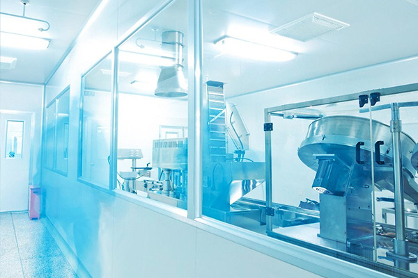
Composition and equipment layout of the compressed air station
In addition to the machine room, an auxiliary room should be provided for the compressed air station. The composition and area should be determined based on comprehensive factors such as the scale of the compressed air station, the type of air compressor, the maintenance system, operation management, and internal corporate cooperation conditions.
The arrangement of equipment in the machine room and auxiliary rooms, as well as the arrangement of other buildings adjacent to the machine room, should not affect the natural ventilation and lighting of the machine room.
The intake filter device of the centrifugal air compressor should be arranged independently, and the connecting pipe with the compressor should be short and straight. In severely cold areas, when the oil-immersed intake filter is installed outdoors or in a separate room, there should be measures to prevent freezing and cold.
Compressed air storage tanks should be placed outdoors, preferably on the north side of the machine room. The minimum distance between the vertical storage tank and the outer wall of the machine room should not be less than 1m, and it should not affect lighting and ventilation. For storage tanks with an oil content of no more than 1mg/m3 in the compressed air, if outdoor placement is difficult, it can be placed indoors.
In the machine room of compressed air stations in hot summer and cold winter or hot summer and warm winter areas, measures to reduce heat dissipation from equipment and pipelines should be adopted.
Screw air compressor units and piston air compressor units should be arranged in a single row. The width of the machine room passage should be determined according to the needs of equipment operation, disassembly, and transportation, and the minimum clearance should not be less than the provisions in Table 4.0.6.
Table 4.0.6 Minimum Clearance of Machine Room Passage (m)
|
Name |
Air Compressor Discharge Volume Q(m3/min) |
|||
|
Q < 10 |
10 ≤ Q < 40 |
Q ≥ 40 |
||
|
Main Passage of Machine Room |
Single Row Arrangement |
1.5 |
2.0 |
|
|
Double Row Arrangement |
1.5 |
2.0 |
||
|
Passage between air compressor units or between air compressor and auxiliary equipment |
1.0 |
1.5 |
2.0 |
|
|
Passage between air compressor unit and wall |
0.8 |
1.2 |
1.5 |
|
|
Note: 1 When it is necessary to disassemble and install the nut components connecting the piston rod and crosshead of the air compressor in the passage between the air compressor unit and the wall, 1.5 the value in the table should be appropriately increased; 2 When arranging equipment, in addition to ensuring that the piston components in the cylinder, the cores in the cooler, and the rotor or stator of the motor can be removed for maintenance, there should also be a margin of no less than 0.5m ; as shown in Table 4.0.6 If the spacing listed in the table does not meet the requirements, it should be increased; 3 The passage for operation and maintenance of the drying device should not be less than 1.5m。 |
||||
Name Air Compressor Discharge Volume Q(m3/min)
Q<10 10≤Q<40 Q≥40
Main Passage of Machine Room Single Row Arrangement 1.5 2.0
Double Row Arrangement 1.5 2.0
Passage between air compressor units or between air compressor and auxiliary equipment 1.0 1.5 2.0
Passage between air compressor unit and wall 0.8 1.2 1.5
Note: 1 When it is necessary to disassemble and install the nut components connecting the piston rod and crosshead of the air compressor in the passage between the air compressor unit and the wall, the value of 1.5 in the table should be appropriately increased;
2 When arranging equipment, in addition to ensuring that the piston components in the cylinder, the cores in the cooler, and the rotor or stator of the motor can be removed for maintenance, there should be a margin of no less than 0.5m; if the spacing listed in Table 4.0.6 does not meet the requirements, it should be increased;
3 The passage for operation and maintenance of the drying device should not be less than 1.5m.
The equipment arrangement of the centrifugal air compressor unit can adopt a single-layer or double-layer arrangement.
When adopting a double-layer arrangement, the following requirements should be met:
1 It is advisable to adopt a full-paved running layer type. The bottom layer should be used for auxiliary equipment, and a maintenance area can be set up next to the unit on the running layer;
2 The lubricating oil supply device should be arranged on the bottom layer. The height difference between the bottom plate and the main oil pump inlet should meet the oil suction height requirements of the main oil pump;
3 The bottom layer and running layer of the machine room should have longitudinal passages running through the entire machine room, with a minimum net width of 1.2m. The minimum distance of the passage next to the unit should meet the requirements for disassembly and installation of the compressor, motor, cooler and other main equipment, the lifting range of lifting equipment, and the distance between equipment foundation and building foundation;
4 There should be no less than 2 entrances and exits on each floor of the machine room, and the running layer should have a safety ladder leading to the ground outside;
5 At the expansion end of the machine room, an installation and maintenance hoisting hole should be left on the running layer. When the bottom equipment needs to be lifted by a traveling crane, a corresponding hoisting hole should also be left on the running layer above the equipment. When adopting a single-layer arrangement, there should also be no less than 2 entrances and exits in the machine room.
The height of the bottom of the high-level oil tank of the centrifugal air compressor unit from the horizontal center line of the unit should not be less than 5m.
When the air drying and purification device is installed in the compressed air station, it should be placed at the end near the auxiliary room. When the user requires a compressed air pressure dew point below -40℃, or the dust particle size is less than 1um, the air drying and purification device should be installed at the user's location.
In the compressed air station, when it is necessary to set up a special maintenance area, its area should not be larger than the area required for the land occupation and operation of the largest air compressor unit.
Compressed air stations with a single discharge volume equal to or greater than 20m3/min and a total installed capacity equal to or greater than 60m3/min should be equipped with maintenance lifting equipment, and its lifting capacity should be determined according to the heaviest component of the air compressor unit.
The coupling and belt drive parts of the air compressor unit must be equipped with safety protection facilities.
When the vertical cylinder head of the air compressor is 3m above the ground, a mobile or removable maintenance platform and ladder should be provided.
The intake air filter should be installed in a place that is easy to maintain. If necessary, a platform and ladder should be provided. The platform, ladder, pit, and the surrounding area of the lifting equipment should be equipped with guardrails. The lower part of the guardrails should be equipped with a protective net or plate. The ditches in the compressed air station should be able to drain accumulated water and should be covered with plates.
Application Industry
Relevant Cases
Product Consultation
Dedicated to provide you with quality products and professional services, please keep the phone open, We will contact you as soon as possible, thank you for your support!


